Magnetron Sputtering Equipment
Magnetron sputtering takes place inside a vacuum chamber to create a low-pressure environment. The target material, typically the material to be deposited as a thin film, is suspended inside the vacuum chamber. An inert gas, often argon, is introduced into the vacuum chamber. This gas will act as the working medium for the sputtering process. The gas atoms are ionized to form a plasma by applying a high voltage between the target (cathode) and a suspended anode.
The target material is negatively charged and serves as the cathode, while the anode is positively charged. This voltage difference creates an electric field that accelerates the positively charged gas ions towards the cathode. The accelerated gas ions strike the target material with high velocity. Upon impact, the ions transfer their momentum and energy to the target atoms. This leads to the ejection of atoms from the target surface.
The ejected atoms from the target surface move across the vacuum chamber and then condense onto the substrate, which moves under the target. This deposition process forms a thin film of the target material on the substrate.
This process can be performed in an inert gas like argon to deposit metal films, in oxygen to deposit oxides, or in nitrogen to deposit nitrides. By using multiple cathodes with different target materials placed next to each other, it is possible to deposit complex coating stacks in one pass through the coater. Each cathode can be made of a different material, allowing for the sequential deposition of various layers to create multilayered structures or tailored material combinations.
Magnetron sputtering is a widely used technology for large area sputtering owing to its ability to apply thin coatings uniformly and reproducibly over wide substrates. There are two main types of magnetron sputtering cathodes: planar and rotatable (also known as rotary or cylindrical ) targets.
Rotatable targets offer several advantages over planar targets. Firstly, rotatable targets increase the utilization of the sputter target material because the erosion of the target material is uniformly distributed over the circumference of the rotary target. The target material lasts longer and therefore the time between target changes is increased, which reduces production downtime.
Secondly, rotatable targets increase the sputter deposition rate. By applying a higher average sputtering power to the hollow cylindrical target, the deposition rate can be increased relative to planar magnetrons. The additional heat generated can be effectively dissipated with higher water flows, allowing for higher power application.
AGC Plasma Technology Solutions has its own design for the key components of both planar and rotary magnetron cathodes.
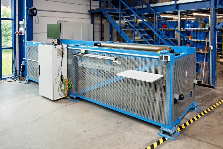
The magnet bar inside the cathode plays a crucial role for the uniformity of the sputtered coating. For retrofitting an existing installation or tuning a new installation, AGC Plasma Technology Solutions offers the Magnetic Field Mapper as a support tool. The Magnetic Field Mapper is designed to assist in correcting and adjusting the intensity of magnet cores in magnetron sputtering systems.
The Magnetic Field Mapper utilizes a magnetic field probe (Hall probe) to measure the intensity of the magnetic field across the full width of the magnet bar, which can be over 3 meters wide. The obtained field profile data is then processed using advanced software developed by AGC Plasma Technology Solutions.
The software includes procedures that allow for the transfer of magnetic field profiles between different magnet cores. Furthermore, the software enables precise adjustment of a magnet core to achieve a specific magnetic field profile. By adapting the magnetic field profile appropriately, the software facilitates the tailoring of coating thickness profiles.
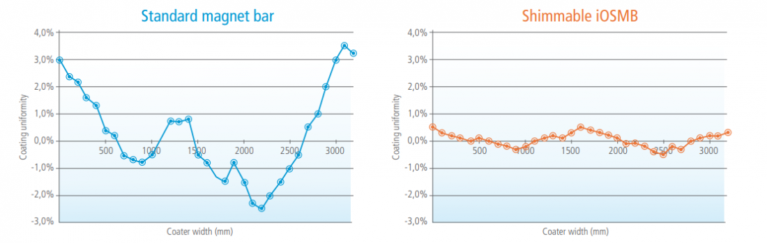
AGC Plasma Technology Solutions developed a technology called iOSMB (Online Shimmable Magnet Bar) which enhances this capability. The iOSMB magnet bar consists of a series of individual magnets called yokes. Each yoke has a length ranging from 110 mm to 220 mm. The height of each yoke relative to the target surface can be adjusted using motors controlled by integrated electronics. This means that the magnetic field strength along the entire length of the cathode can be precisely controlled at a local level. By independently controlling each individual yoke, users have unprecedented control over the coating thickness uniformity across large area substrates and even curved objects.
An important feature of the iOSMB technology is that it operates on a battery-powered system. This means that there are no external electrical connections required during operation, providing convenience and flexibility in the setup and use of the magnet bar.
Features
- Reduces the tuning time for complex multi-stack coatings or coatings on complex parts like curved 2D or 3D objects
- Allows the local adjustment of magnetic field during the production without the need to switch off the plasma or to vent the coater to adjust the deposition rate and correct for non-uniformities
- An integrated tuning wizard shows the effects of changes to magnet yoke settings on resulting layer profile uniformity to guide the operator in making the right decisions. An easy-to-use graphical interface allows the operator to control the settings of the individual yokes of the iOSMB by graphical sliders
- It is possible to transfer a magnetic field between different iOSMBs. This allows replacing magnet bars easily without changing the magnetic field strength distribution